“IBC2000E” — IBC 2000 SEISMIC ANALYSIS PROGRAM
Program Description:
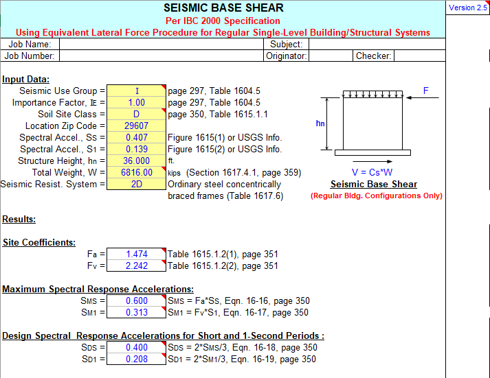
“IBC2000E” is a spreadsheet program written in MS-Excel for the purpose of seismic loading analysis for
buildings and various nonbuilding structures, as well as architectural, mechanical, and electrical components
per the IBC 2000 Code. Specifically, the total base seismic shear for buildings and nonbuilding structures is
calculated. For Multi-Level Buildings, the vertical distribution of the total seismic shear is also determined, and
a drift analysis can also be performed. The seismic restraint force for various components is also calculated.
This program is a workbook consisting of ten (10) worksheets, described as follows:
Worksheet Name Description
Doc This documentation sheet
Single-Level Bldg. Seismic base shear for single-level buildings
Multi-Level Bldg. Seismic base shear and vertical shear distribution for multi-level buildings
Multi-Level Bldg. (Drift) Seismic story drift analysis for multi-level buildings
Steel Vert. Tank or Vessel Seismic base shear and overturning moment for vertical steel tanks/vessels
Nonbldg. Struct. Seismic base shear and overturning moment for nonbuilding structures
Arch. Components Seismic force for architectural components
M & E Components Seismic force for mechanical and electrical components
Maps for Ss 1996 NEHRP (USGS) maps for 0.2 sec. spectral acceleration with 2% P.E.
Maps for S1 1996 NEHRP (USGS) maps for 1.0 sec. spectral acceleration with 2% P.E.
Program Assumptions and Limitations:
- For buildings, the program assumes the use of the equivalent lateral-force method for analysis, per Section
1617.4. For nonbuilding structures, Section 1622 is followed. For architectural, mechanical, and electrical
components, Section 1621 is followed. The “simplified” method, per Section 1617.5, is not used in any of the
calculation worksheets. - The program assumes “regular” buildings and structures, with plan and vertical irregularities not being
considered. Refer to Section 1616.5 for building configuration, and plan and vertical irregularity criteria. - Worksheets for Multi-Level Buildings are applicable for buildings and structures up to 240 feet in height, with
up to 15 levels. (Story deflections are to be determined from separate elastic 2D or 3D frame analysis.) - This program does not include the provisions for nonbuilding structures that are supported by other
structures as per Section 1622.1.1. - Worksheets calculate for “gross” seismic shear force, and do not reflect the use of any load factors. Refer to
Section 1605.2 and 1605.3 for applicable loads factors for LRFD or strength design as well as ASD analysis. - The NEHRP (USGS) Maps for the short term 0.2 sec. spectral acceleration (SA) with 2% Probability of
Exceedance in 50 years, Ss, as well as the 1.0 sec. spectral acceleration (SA) with 2% Probability of
Exceedance in 50 years, S1, are included. These maps are the 1996 “color versions” of Figures 1615(1)
and 1615(2) from the IBC 2000. Peak gravitational acceleration, PGA, is what is experienced by a particle on
the ground. Response spectral acceleration, SA, is what is approximately experienced by a building, as
modeled by a particle on a massless vertical rod having the same natural period of vibration as the building.
The SA values shown in the USGS maps as well as the IBC Figures 1615(1) through 1615(10) are expressed
as a percentage of “g”, the acceleration due to gravity. Their numerical values should be divided by 100 to
convert them into decimal form for use in the Code formulas and calculations.) Note that there are “exploded”
maps of various portions of continental U.S. included as well. These can be seen by scrolling down screen.
(Note: while the USGS does have later, 2002 gridded design values for Ss and S1 available at their web site,
the user is cautioned in their use as they are NOT officially adopted for use by IBC 2000 Code. If their use
would result in a lower Seismic Design Category and reduced seismic loads, the user is advised to seek
formal approval of their use by the owner and building official if applicable.) - This program allows the user to select only site classes “A” through “E”, since site class “F” requires
site-specific geotechnical investigation and dynamic site response analyses. These same requirements also
apply for site class “E”, but only when Ss >= 1.25g and S1 >= 0.5g. - In the calculation worksheets, a “hyperlink” is provided to take the user directly to the USGS website at:
http://earthquake.usgs.gov/research/hazmaps/
Once finished at the USGS website, the user should exit the website by pressing the [<-Back] button in the
top toolbar of the web browser to return to the particular program worksheet. - This program automatically selects the appropriate seismic response modifier, “R” for buildings and
structures and “Rp” for components, once the type of seismic resisting system has been selected/input by
the user. - This program will automatically alert the user with a “warning message” when any applicable limitations have
been exceeded for the particular seismic resisting system selected. - For reference, at right side of the display, the calculation worksheets contain some representative 1996
gridded USGS spectral acceleration (SA) values for 5 particular zip code locations (and the applicable cities),
as well as copies of the tables of seismic coefficients and factors to be used. - This program contains numerous “comment boxes” which contain a wide variety of information including
explanations of input or output items, equations used, data tables, etc. (Note: presence of a “comment box”
is denoted by a “red triangle” in the upper right-hand corner of a cell. Merely move the mouse pointer to the
desired cell to view the contents of that particular “comment box”.)


